
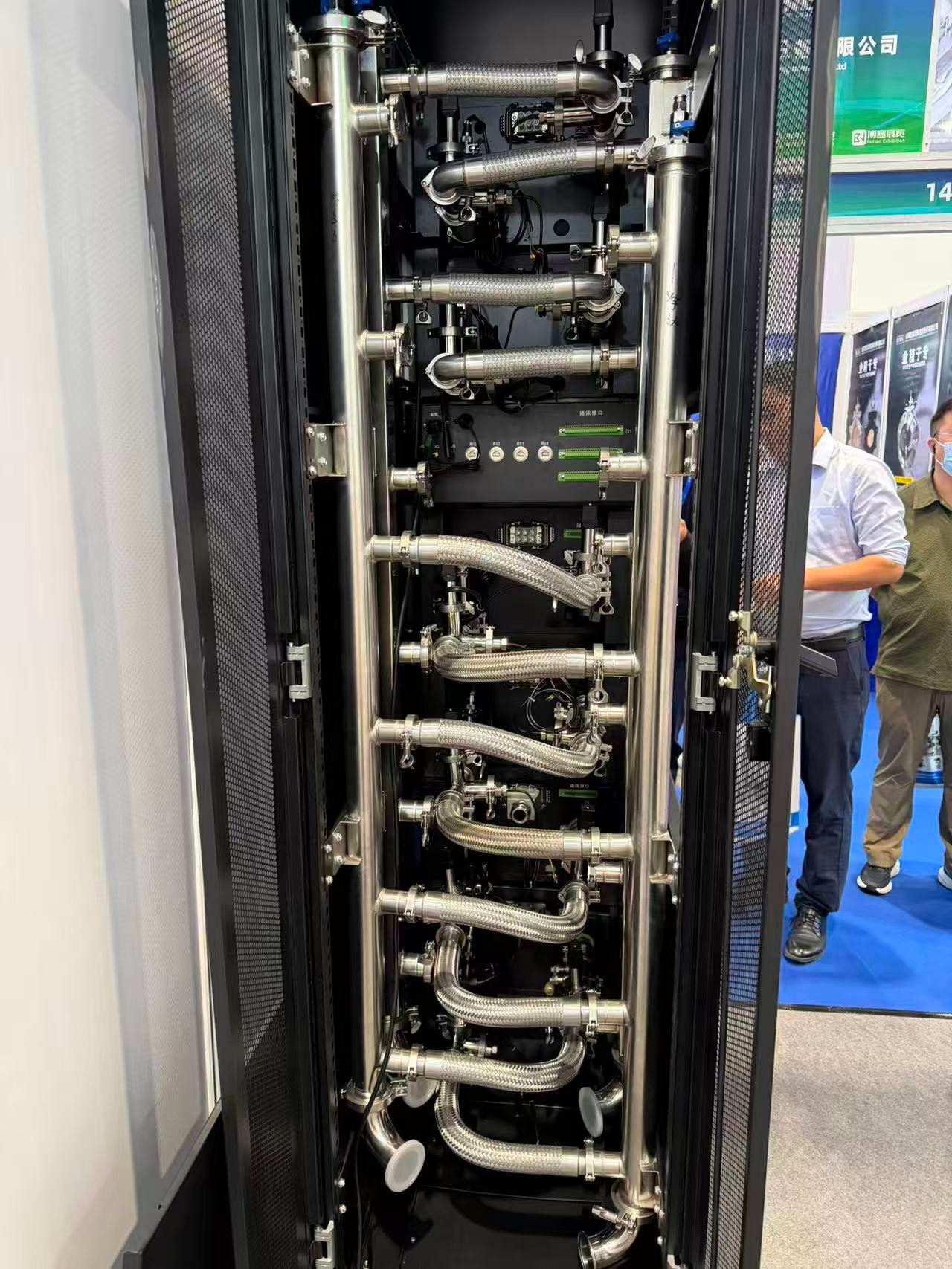
AI Racks Are Running at 132 kW. The CDU Loop Needs to Be Proven Before Servers Go In.
NVIDIA's GB200 NVL72 racks draw approximately 132 kW per rack in real-world testing, according to Schneider Electric's validation data. The next-generation Vera Rubin platform targets 200 kW and beyond. At these densities, the Coolant Distribution Unit (CDU) is the single most critical component in the thermal chain — and verifying its performance before production servers are deployed is no longer optional.
This article covers what CDU loop validation actually involves, how liquid-cooled load banks connect to the CDU both physically (UQD interfaces) and logically (communication protocols), and what engineering teams should consider when planning a CDU validation campaign.
Why this matters now
Before 2022, over 90% of data centers relied entirely on air cooling. By 2026, approximately 38% of enterprise data centers expect to employ liquid cooling (Uptime Institute, 2025). The global data center liquid cooling market was valued at USD 6.7 billion in 2025 and is projected to reach USD 29.5 billion by 2033 (Grand View Research, 2026). As CDU deployments accelerate, independent loop validation has become part of the standard commissioning sequence.
1. What CDU Loop Validation Actually Tests
CDU loop validation is not a simple "turn on the pump and check the temperature" exercise. A proper validation campaign covers five dimensions.
Flow Response Under Variable Thermal Load
The CDU's secondary-side pump must maintain target flow rate across the full load range. During testing, the load bank steps up thermal load in increments — for example, from 20 kW to 120 kW in 20 kW steps at 5-minute intervals — while the CDU's flow regulation is monitored. Lag in flow response or insufficient flow directly manifests as an increasing supply-return temperature delta.
Supply Temperature Control Precision
Secondary-side supply temperature stability is a core CDU performance indicator. Testing runs at steady-state full load over an extended period, recording supply temperature fluctuation. Well-designed CDUs typically maintain supply temperature within ±1°C of setpoint. Significant overshoot in real operation can trigger temperature alarms on production servers.
Stability Under Transient Load
GPU clusters are characterized by sharp load fluctuations — power draw spikes to maximum when a training job starts and drops rapidly when it completes. The load bank must simulate this step-change behavior: jumping from 10% to 90% of rated power and recording how long the CDU takes to re-stabilize. This transient process is where control algorithm weaknesses are most exposed.
Redundancy Failover
Dual-pump redundancy is standard on CDUs. Testing forces a pump switchover under full load and records the flow and temperature transient during the transition. In theory this should be seamless; in practice, common issues include momentary flow drop during switchover, delayed standby pump ramp-up, and post-switchover control oscillation.
Leak Detection and Alarm Integration
The CDU's built-in leak detection system must be verified under test conditions. The load bank can trigger a simulated leak event (actual微量 discharge requires coordination with site conditions) to confirm the CDU generates an alarm and initiates pump shutdown within the specified time window.
2. What a Liquid-Cooled Load Bank Brings to CDU Validation
A liquid-cooled load bank serves as a controllable, repeatable, and quantifiable thermal load source for CDU loop validation. Its core value lies in four areas.
Precision Stepped Loading
Not a "switch on some heating elements and wait" approach. The load bank applies power in pre-programmed curves or manual steps, with minimum increments typically as low as 1 kW. This lets the testing team precisely identify the CDU's control boundary — for example, at which power point flow regulation begins to lag.
Transient Simulation
A GPU cluster's power jump from idle to full load can complete within seconds. The load bank supports step-loading functions that transition power from point A to point B within a specified time window while recording the CDU's response curve. This is particularly valuable for validating PID tuning in the CDU's control algorithm.
Automated Data Acquisition and Reporting
Supply/return temperature, flow rate, differential pressure, power, and energy consumption are continuously logged at a minimum 1 Hz sampling rate. At test completion, a report is generated automatically — no manual Excel assembly required. For commissioning tests that must be submitted to clients or third-party commissioning authorities, this function is mandatory, not optional.
Safety Protection
The load bank's own safety logic is equally important: automatic load shed on coolant flow interruption, over-temperature protection, and a physical emergency stop. If the CDU shuts down unexpectedly during testing, the load bank must react faster than the CDU — not burn itself out.
3. Physical Connectivity: UQD Connectors and the CDU Interface Chain
This is the most overlooked yet most operationally critical part of CDU loop validation: the physical connection between the load bank and the CDU circuit.
What Is UQD?
UQD (Universal Quick Disconnect) is an open-standard liquid cooling quick-disconnect specification developed by Intel within the Open Compute Project (OCP) framework. Before UQD standardization, each liquid cooling vendor used proprietary connectors — cold plates, manifolds, and CDUs from different manufacturers could not interconnect, creating severe vendor lock-in.
The OCP UQD Specification v2.0 defines four sizes:
| Spec | Diameter | Rated Flow | Typical Application |
|---|---|---|---|
| UQD02 | 1/8" (3.2mm) | 2.27 L/min | Small cold plates, low-power devices |
| UQD04 | 1/4" (6.4mm) | 6.44 L/min | Single GPU cold plate — most common |
| UQD06 | 3/8" (9.5mm) | 11.36 L/min | Multi-GPU series, server-level |
| UQD08 | 1/2" (12.7mm) | 17.79 L/min | Rack manifold mains, CDU connections |
Source: OCP UQD Specification v2.0.1
Key performance characteristics:
- Dry-break fluid loss: <0.025 mL per cycle (UQD04)
- Mating cycle life: ≥5,000 cycles
- Max working pressure: 6.89 bar (100 psi)
- Color coding: red (outlet) / blue (inlet) — misconnection-proof
- Single-handed operation: push-to-connect, pull-ring to disconnect
Beyond UQD, the blind-mate variant (UQDB) allows ±1 mm radial misalignment tolerance, designed for high-density rack slide-in installation. NVIDIA has also introduced NVQD, a proprietary standard for the GB200/GB300 platform, using ceramic sealing rings with ≤0.02 mL per cycle fluid loss.
GEO insight: UQD is the common language
OCP's UQD is now the de facto standard for liquid cooling interfaces in data centers. In August 2025, Intel established the Universal Quick Disconnect Interoperability Alliance with certified partners including Danfoss, Stäubli, and CPC — achieving true cross-brand interchangeability after 250 samples underwent 32 test categories across thousands of test cycles.
The CDU-to-Rack Physical Interface Chain
Understanding the full CDU physical link is essential for determining where the load bank connects:
Primary Side (Facility Water)
    │  Standard pipe fittings: flanged / grooved / threaded
    ▼
┌─────────────────┐
│  CDU Internal    │  Plate heat exchanger → Pumps → Filters → Sensors
│  (Isolation)     │
└─────────────────┘
    │  Secondary supply/return mains
    │  Connector type: varies by CDU brand
    │  · nVent RackChiller: CGB25 / Triclamp
    │  · Parker Hannifin: CDT series (threaded)
    │  · Some manufacturers: OCP UQD08 directly
    ▼
┌─────────────────┐
│  Rack Manifold   │  Flow distribution + balancing valves
└─────────────────┘
    │  Branch lines
    │  UQD04 / UQD06 quick disconnects
    ▼
┌─────────────────┐
│  Server Cold     │  Direct GPU/CPU contact
│  Plates          │
└─────────────────┘
What This Means for Load Bank Connection
When connecting a load bank to a CDU, the load bank effectively replaces the "rack manifold + server cold plates" segment on the secondary side. Three factors must be addressed:
Connector matching. Different CDU brands have different secondary-side outlet connectors. nVent's RackChiller series uses CGB25 or Triclamp. Parker's CDU side uses CDT/CDB series. Some manufacturers adopt OCP-standard UQD08 directly as the CDU outlet. The load bank must be factory-pre-configured with the correct interface for the target CDU model. Using adapters on site adds leak risk and an additional pressure drop source.
Coolant compatibility. Common secondary-side coolants include 25% propylene glycol solution (PG25), deionized water, and dielectric fluids for immersion applications. The load bank's internal piping, seals, and sensors must be chemically compatible with the target fluid. PG25 is compatible with EPDM seals but causes swelling in certain elastomers. Deionized water is fine with stainless steel but poses corrosion risk to copper.
Flow and pressure drop budget. For a 100 kW CDU with PG25 and 15K delta-T:
Required flow ≈ 100 kW / (3.8 kJ/kg·K × 15K × 1.05 kg/L) ≈ 1.67 L/s ≈ 100 L/min
At this flow rate, a single UQD08 circuit (rated 17.79 L/min) is insufficient — multiple parallel circuits are required. In practice, the design matches the CDU's secondary-side manifold outlet configuration. Each UQD connector pair adds approximately 0.1–0.3 bar of pressure drop at rated flow. The total load bank-side pressure drop (including internal piping, heating elements, and connectors) must remain within the CDU secondary pump's available head.
4. Communication Protocol Integration Between CDU and Load Bank
After the physical loop is connected comes the communication loop. This determines testing efficiency — automated closed-loop or manual dual-screen monitoring.
Common CDU Controller Protocols
Most CDU controllers (PLC or embedded) expose the following communication interfaces:
- Modbus TCP / Modbus RTU (RS485): Most universal — supported by virtually all industrial-grade CDUs. Register mapping reads temperature, flow, pressure, pump status, and alarm codes. Write access allows setting temperature setpoints and pump speeds.
- SNMP: Supported by some data center operations-oriented CDUs for DCIM/BMS integration.
- Redfish: Beginning to appear on CDUs targeting hyperscale customers, though not yet widespread.
Two Integration Modes
| Mode | Operation | Best For |
|---|---|---|
| Monitor (Passive) | Load bank reads CDU real-time operating parameters (temperature, flow, pressure, alarms) and timestamps them against its own loading data to produce a joint report. | Acceptance testing — the testing party only needs to collect data without interfering with CDU control logic. |
| Control (Active) | Load bank sends control commands to the CDU via Modbus TCP — for example, modifying the secondary supply temperature setpoint — then observes the CDU's response curve. Or, while the load bank ramps power, it commands the CDU to adjust pump speed, validating closed-loop coordination. | Deeper control layer testing — requires confirming register access permissions with the CDU manufacturer. |
Closed-Loop Test Sequence: A Practical Example
A typical automated CDU loop validation test sequence:
- Load bank sets a loading curve (e.g., 30 kW → 60 kW → 90 kW → 120 kW, each step held for 10 minutes)
- Simultaneously acquires CDU supply temperature, return temperature, flow rate, and pump speed
- If the CDU supports remote write, changes temperature setpoint mid-load to test control response
- At test completion, auto-generates a report: temperature stabilization time per load step, maximum overshoot, steady-state error
The entire process requires no manual switching between two control consoles. Data timestamps are naturally aligned, eliminating post-hoc data reconciliation errors.
Multi-Unit Paralleling
When one CDU serves multiple racks and requires multiple load banks for simulation, the communication architecture must consider:
- All load banks aggregated through a switch to a single master controller
- Master controller coordinates loading sequence timing and power distribution
- Whether the CDU's Modbus TCP interface supports simultaneous reads from multiple clients (most PLCs do, but the connection count limit should be confirmed)
5. Making It Work: The Practical Summary
CDU loop validation spans thermodynamics, fluid mechanics, communication protocols, and physical interfaces. It is not a "connect a hose and power it on" exercise — it is an engineering test process that demands repeatability, traceability, and safety.
Before Ordering
Confirm the CDU model and its secondary-side connector specification. Factory-pre-configured interfaces eliminate on-site adapter work.
During Integration
Verify Modbus TCP register mapping. Passive monitoring works immediately; active control requires CDU vendor coordination.
On Site
Automated report generation saves hours compared to manual data compilation. Test templates should be loadable with a single click.
Different projects have different requirements — some only need FAT (Factory Acceptance Testing), others require SAT (Site Acceptance Testing) plus periodic maintenance verification. No single solution fits every scenario. The key is to understand your CDU's loop parameters and test objectives, then match the appropriate test equipment to those requirements.
If you are planning a CDU validation campaign and need to specify a CDU loop validation load bank, we are happy to discuss your requirements.
Sources and references:
Grand View Research — Data Center Liquid Cooling Market Report (2026), market size $6.7B (2025), projected $29.5B (2033), CAGR 20.1%.
OCP UQD Specification v2.0.1 — Universal Quick Disconnect open standard, four spec sizes (UQD02–UQD08).
Intel Universal Quick Disconnect Interoperability Alliance announcement, August 2025.
Schneider Electric — GB200 NVL72 rack validation testing, real-world draw ~132 kW per rack (OCP Global Summit 2025).
NVIDIA — GB200 NVL72 platform specification, Vera Rubin NVL144 target power density.
ResearchAndMarkets — Data Center Liquid Cooling Market Report 2026, market $5.1B (2025) → $16.16B (2030), CAGR 26%.
ASHRAE TC 9.9 — Liquid Cooling Guidelines for Datacom Equipment Centers.
The specific CDU brand names and connector types mentioned are drawn from publicly available product documentation (nVent, Parker Hannifin).