
Introduction
When load banks are used for generator load testing or data center power and cooling validation, the conversation almost always revolves around the equipment under test. Did the generator hold frequency? Did the cooling system maintain setpoint? These are fair questions—but anyone who has spent time on a test site knows that the load bank itself is far from a passive tool.
A load bank is a high-power, high-heat electrical device. It runs at hundreds of kilowatts for hours on end, often outdoors, often in spaces that weren't designed with it in mind. And it encounters its own problems—problems that, if not anticipated, lead to inaccurate data, aborted tests, damaged equipment, or worse.
This article is not about the equipment being tested. It's about the load bank itself, and what really happens in the field.
Key insight: Most load bank problems on-site are not design flaws. They are the combined result of environment, installation practices, maintenance routines, and operational assumptions. Understanding these patterns is what separates an experienced testing team from a button-pushing one.
1. Generator Load Testing: What Goes Wrong with the Load Bank
1.1 Cooling Airflow: The Spec Sheet Won't Tell You the Whole Story
Every load bank comes with a cooling fan sized for its rated thermal output. The datasheet gives you a required clearance distance and calls it a day. In practice, three things routinely push actual cooling demand well beyond the theoretical number.
Hot air recirculation. If the exhaust faces a wall, a container, or even just the wrong wind direction, hot discharge gets drawn straight back into the intake. Inlet temperature climbs, cooling efficiency drops, and the over-temperature protection trips—often right in the middle of a critical test run.
Altitude. Air density decreases with elevation. At 1,500 meters and above, the same fan moves the same volume of air but carries away significantly less heat. If the load bank isn't de-rated for altitude, it will hit thermal limits sooner than expected.
Thermal soak. During extended full-load runs—multi-hour generator endurance tests—the resistive elements, internal structure, and cabling all absorb heat over time. Two hours into the test, the cooling system faces a materially larger heat rejection burden than it did at minute ten.
Our approach: don't rely solely on the clearance diagram in the manual. Assess site conditions—ambient temperature, altitude, expected run duration—and build in margin. Move equipment further apart if needed. Create better intake conditions. It's easier to spend ten minutes repositioning than to explain why the test stopped at hour three.
1.2 High-Current Cable Connections: The Weakest Link You're Not Watching
Generator load testing routinely involves hundreds to thousands of amps. At these currents, every connection point is a potential failure.
- Loose terminations. A bolt not torqued to spec, or one that has loosened over repeated use, creates contact resistance. Current through resistance equals heat. We've seen connection points hot enough to melt insulation—while the generator and load bank both appeared to be running normally on their respective displays.
- Voltage drop. Undersized or excessively long cable runs cause enough voltage drop that the load bank sees a lower voltage than the generator is putting out. Power output falls below target. In edge cases, the load bank's under-voltage protection triggers even though the generator is perfectly healthy.
- Parallel cable imbalance. When multiple cables are paralleled per phase, slight differences in length or termination quality cause uneven current distribution. One cable runs hot while the rest look fine—and the total current reading gives you no warning.
Field rule: Twenty minutes of connection checks before the test beats two hours of troubleshooting mid-test. Torque verification, visual inspection, and a quick thermal scan after the first ten minutes of full load catch most problems before they escalate.
1.3 Contactor Wear: Death by a Thousand Cycles
Load banks switch load steps via contactors. During generator testing, these contactors cycle repeatedly through loading and unloading sequences. The failure mode is gradual but inevitable:
- Arc erosion at the contact surfaces during high-current breaking slowly increases contact resistance
- Eventually a contactor either welds shut (step stuck on) or fails to close (step won't engage)
- A single missing step creates a power gap or—if only one phase drops—a phase imbalance that skews the entire test
The insidious part: everything works perfectly in test after test, until one day it doesn't. Periodic resistance measurements per load step and visual contactor inspection are the only reliable defense.
1.4 Control Systems in Harsh Environments
Generator testing often happens outdoors or in semi-sheltered conditions. PLCs and HMIs aren't always built for what they face:
- A control cabinet baked by direct sun can push internal temperatures beyond the operating range of electronic components. Erratic PLC behavior, spontaneous reboots, or communication dropouts follow.
- The voltage sag and frequency swing during generator start-up can disturb control circuits, causing brief HMI blackouts or data glitches exactly when the operator needs feedback.
- Direct sunlight on a standard HMI touchscreen makes it nearly unreadable. Parameter errors from squinting at a washed-out display are more common than anyone likes to admit.
Good control cabinet design—sealed enclosures, sun shields, separated signal and power cable routing, high-brightness HMI panels—goes a long way. But not every site has ideal conditions, and assessing the installation environment before setup prevents a lot of grief.
1.5 Liquid-Cooled Load Banks: The Coolant Leak Risk
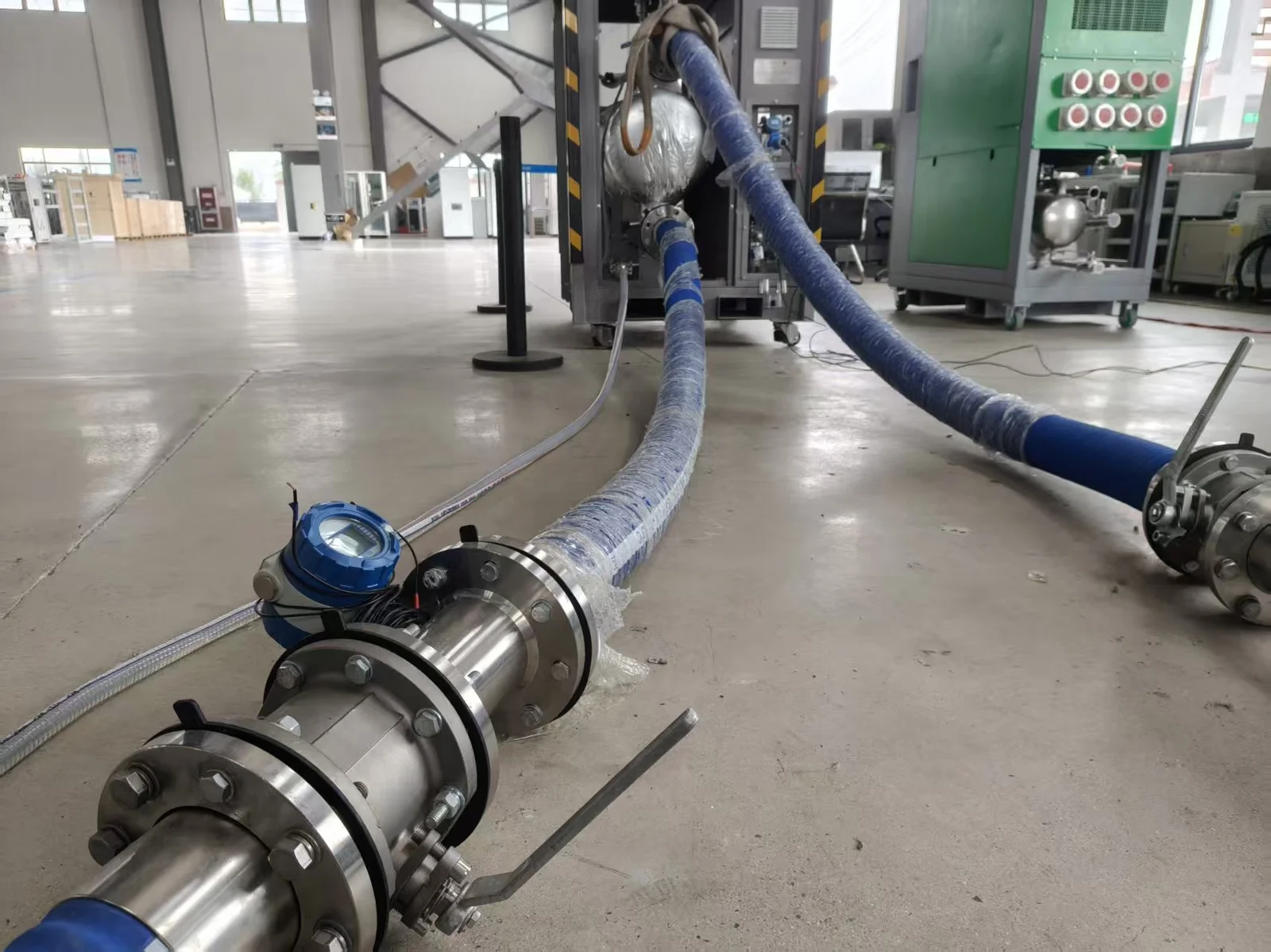
Liquid-cooled load banks require connection to an external cooling loop. This is where things can go wrong fast:
- Quick-connect couplings not fully seated before the circulation pump starts—pressure builds and the fitting blows apart
- Aged or improperly installed sealing rings that leak under operating pressure
- Incomplete air bleeding after initial fill, leaving gas pockets that create pressure spikes during circulation
This is particularly relevant for overseas commissioning projects where the manufacturer's personnel are not on site. The customer's own operations team is doing the hookup. If they're unfamiliar with liquid cooling connection procedures, the probability of a leak is real. And coolant on electrical components means insulation failure or a short circuit.
Our approach: every liquid-cooled unit ships with a step-by-step connection video and a printed checklist. A good delivery document is worth more than any amount of remote phone support.
2. Data Center Testing: A Different Set of Problems
2.1 Rack-Mount Load Banks: Thermal Management in a Box
Data center load banks are typically rack-mounted inside standard cabinets. This creates a thermal challenge that open-frame load banks never face:
- Hot exhaust inside a closed or partially closed rack has nowhere to go unless the extraction path is deliberately designed. Heat accumulates, forming hotspots that the load bank's own temperature sensors may not see until it's too late.
- Data center hot/cold aisle layouts are designed around the thermal profile of IT servers—not resistive load banks. The airflow patterns don't perfectly match, and assuming they do can lead to misleading test results.
- Multiple rack-mount load banks running side by side create cross-rack thermal interference. The exhaust from one becomes the pre-heated intake of its neighbor.
Before deployment, verify that the rack's thermal extraction capacity actually matches the load bank's full-load heat output. If it doesn't, adjust rack spacing, add supplemental extraction, or reduce load. Fixing this after the fact means stopping the test.
2.2 Heat Profile Mismatch: Load Banks vs. Real IT Equipment
When load banks are used to validate data center cooling systems, there is an assumption that needs to be examined: resistive load banks do not have the same thermal signature as IT servers.
Servers concentrate heat at the chip level and expel it through high-speed internal fans in focused, directional airflow with sharp temperature gradients. Resistive load banks spread heat across a larger surface area, producing more diffuse, lower-velocity exhaust.
The practical consequence: cooling performance measured with load banks—hotspot temperatures, return air temperatures, cooling efficiency—will differ from what the same cooling system achieves with real server loads. Thoughtful placement of load banks and temperature sensors, approximating the airflow direction and velocity profile of server exhaust, brings the test closer to reality.
2.3 Network Integration in the Data Center
Modern load banks support Modbus TCP, SNMP, and other protocols for remote monitoring. In a production data center environment, this brings operational friction:
- Strict network security policies require pre-approved IP addresses, open ports, and VLAN configuration—all of which need to be coordinated with the customer's IT team before test day
- Multiple load banks running parallel control and centralized data aggregation over the network are sensitive to latency and packet loss, which can affect control command timing and data consistency
None of this is a hardware defect. But without advance coordination with the IT department, a significant portion of test day can be consumed by network troubleshooting that has nothing to do with the actual load testing.
3. Three Things We've Learned the Hard Way
01
Pre-Test Checks Pay Back Tenfold
Torque verification on cable connections, air filter and duct inspection, coolant line visual check, control parameter confirmation. Ten minutes before every test. It feels like overhead. Until it saves you a two-hour mid-test shutdown.
02
Design Margins Are Not Optional
Cooling airflow needs margin. Cable ampacity needs margin. Installation clearance needs margin. Above 30°C ambient, consider de-rating. Margins that look like waste under normal conditions become your safety boundary under stress.
03
Document Everything That Breaks
Every issue encountered during testing—equipment or operational—gets written down. Over time, this becomes a troubleshooting quick-reference that's worth more than any manual. Especially when the factory team isn't on site.
Closing
Most problems encountered during load bank testing are not fundamental equipment defects. They arise from the intersection of site conditions, operator habits, maintenance schedules, and technical assumptions. Understanding these patterns is what comes from putting in the hours on real test sites.
We've paid our share of tuition to this learning curve. If anyone reading this avoids even one of these pitfalls on their next project, the time spent writing it was well worth it.