
I Have a Project to Deliver, a Budget to Spend, and Risks to Manage. Give Me a Solid Reason.
This article draws on our hands-on experience delivering rack-mounted liquid-cooled load banks. It covers four things that come up in nearly every project conversation: customization, factory testing, delivery, and field commissioning.
1. What Can Be Customized
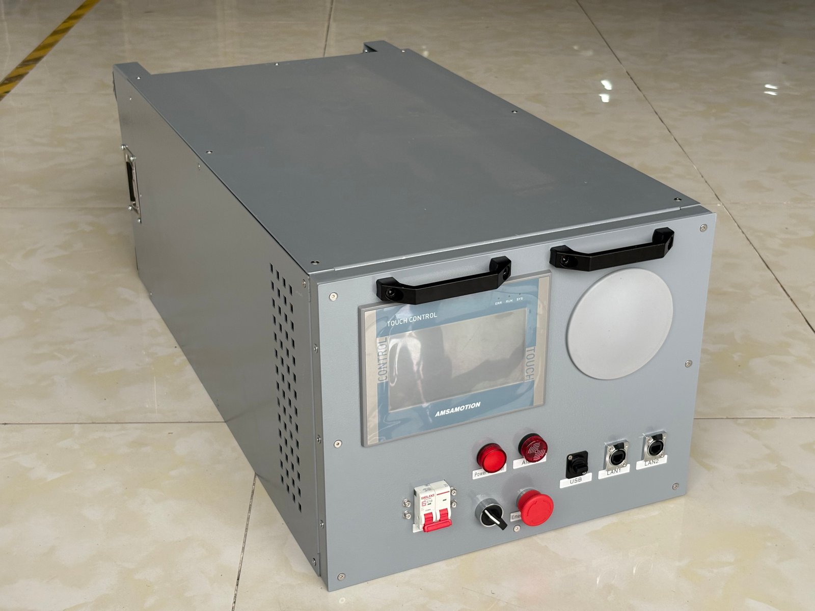
A rack-mounted liquid-cooled load bank is not an off-the-shelf product. It sits on a standard platform, but configuration is adjusted to the project. Here is what you can specify.
Key takeaway
Interface specifications, communication protocols, and paralleling configuration have the biggest impact on lead time. Lock these down during the technical review phase.
Power and Paralleling
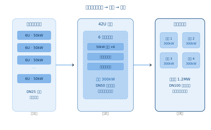
Individual units range from 50 kW to 100 kW. Paralleling works at two levels:
| Level | Description | Example |
|---|---|---|
| Cabinet-level | Multiple load units in one 19-inch rack, electrically and communication-bonded inside the cabinet | A 42U cabinet with 6 units (approx. 7U each, 50 kW) delivers 300 kW per cabinet |
| Cluster-level | Multiple cabinets paralleled, managed by a single host controller | 4 cabinets at 300 kW each, total 1.2 MW |
Load distribution and synchronization are handled by the host software. A single unit failure does not affect the rest.
Liquid Cooling Interfaces
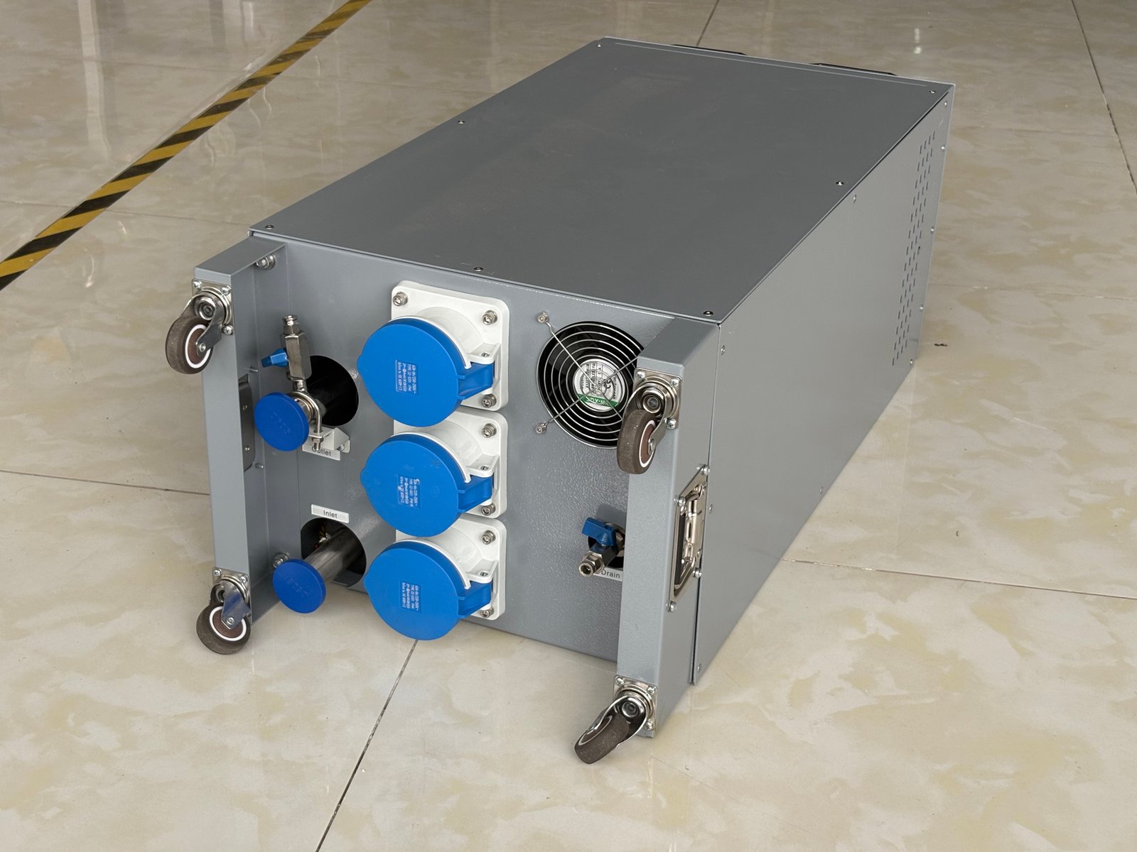
Interface specifications follow the project's cooling loop pipe diameter:
| Spec | Application | Connection Type |
|---|---|---|
| DN25 | Single unit 50-100 kW, low-flow loop | Compression fitting, quick-connect |
| DN50 | Cabinet-level manifold outlet | Flange, quick-connect |
| DN100 | Cluster-level trunk pipe | Flange |
Confirm the site's operating pressure and flow range when specifying the interface.
Electrical Interface
European projects default to 400 V / 50 Hz. Distribution method, cable entry position, and terminal specifications can be adjusted to site conditions.
| Item | Standard | Customizable |
|---|---|---|
| Voltage / Frequency | 400 V / 50 Hz | 480 V / 60 Hz, others |
| Cable entry | Bottom entry | Top entry, side entry |
| Distribution capacity | Matched to unit power | Reserved headroom for expansion |
Communication and Control
Three control tiers are supported:
| Tier | Interface | Protocol | Response |
|---|---|---|---|
| Local | Cabinet touchscreen | — | Real-time |
| Remote | Host software / DCIM | Modbus TCP | LAN ≤ 500 ms |
| Cluster | Host unified scheduler | Modbus TCP / Redfish | Sync interval configurable, default 1 s |
Modbus TCP is standard. Redfish support is evaluated per project. Proprietary protocol adaptation requires additional development time.
Cabinet Adaptation
Standard 19-inch rack format (see product details). Height and depth are adjustable. Panel color, silkscreen logo, and nameplate content are specified per project.
Power range
50 kW to 100 kW per unit. Cabinet-level 300 kW, cluster-level 1.2 MW.
Interface specs
DN25 / DN50 / DN100. Compression, flange, or quick-connect fittings.
Control protocols
Modbus TCP standard. Redfish optional. Proprietary on request.
2. Factory Testing
Every unit completes a full test sequence before shipment. Test reports with measured data are included with the delivery.
Power Step Loading
| Step | Duration | Parameters recorded |
|---|---|---|
| 25% | ≥ 30 min | Three-phase voltage, current, active power, power factor |
| 50% | ≥ 30 min | Above + cooling loop inlet/outlet temperature, flow rate |
| 75% | ≥ 30 min | Same as above |
| 100% | ≥ 2 h | Full parameter set, continuous recording |
Full-load operation runs for at least two hours. All electrical parameters must stay within design tolerance.
Temperature Rise Uniformity
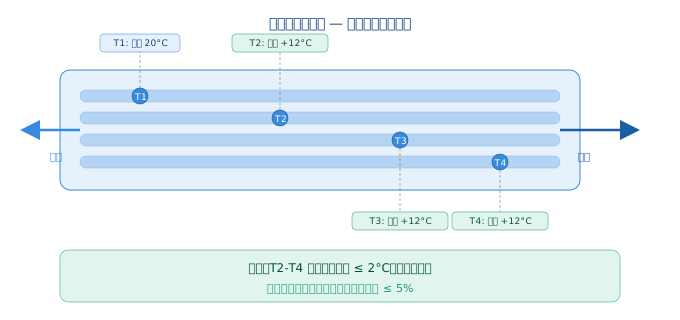
This is the core factory test for liquid-cooled load banks. The goal is not “control precision” but verifying that heat is removed evenly across all flow paths.
Procedure: under full load, place 2–4 temperature sensors at key points along the heat exchanger flow path (typically at the inlet, outlet, and across internal flow channels). Monitor flow rate and pressure simultaneously.
| Check | Criterion |
|---|---|
| Temperature rise deviation between points | ≤ 2 °C |
| Outlet temperature curve | Smooth, no step changes |
| HX inlet-outlet ΔT vs. theoretical | Deviation ≤ 5% |
| Flow stability | Fluctuation ≤ ±3% of rated |
| Line pressure | Within design operating range, no abnormal fluctuation |
If one measurement point shows a noticeably higher temperature rise, the area likely has a cooling flow dead zone — the heat exchanger internal channel design or piping connection needs investigation.
Leak Test
| Parameter | Value |
|---|---|
| Test pressure | 1.5× operating pressure, minimum 6 bar |
| Hold duration | ≥ 30 min |
| Pass criterion | Pressure drop ≤ 0.1 bar, no leakage at any joint or weld |
Note
The internal leak detection sensor must remain dry (not triggered) throughout the test.
Communication and Control Response
Local control: Touchscreen operations respond without perceptible delay. Data refresh cycle ≤ 1 second.
Remote control (Modbus TCP):
| Test | Method | Standard |
|---|---|---|
| Data read | Poll all registers (temperature, power, flow, alarms) | No timeout |
| Command write | Send power setpoint, start/stop, threshold changes | Register values correctly updated |
| Continuous run | 10 minutes sustained communication | Zero packet loss |
Cluster control (minimum 2 units in test):
| Test | Standard |
|---|---|
| Total power distribution | Sum of all subunit setpoints = command value, distribution complete ≤ 2 s |
| Single unit fault isolation | Remaining units auto-rebalance, completion ≤ 3 s |
| Fault recovery rejoin | Load redistributed, cluster resynchronized |
Safety Protection — Triggered Individually
| Protection | Trigger method | Expected response | Response time |
|---|---|---|---|
| Over-temperature | Reduce flow to exceed outlet temp. threshold | Auto load reduction or shutdown | ≤ 2 s |
| Leak detection | Apply liquid to sensor | Alarm + shutdown, displayed on local screen and host | ≤ 2 s |
| Low flow | Close or throttle inlet valve | Alarm + load reduction | ≤ 3 s |
| Emergency stop | Press E-stop button | Main circuit de-energized, all loads disconnected | Immediate |
| Power recovery | Interrupt power 10 s, then restore | Unit stays off, requires manual restart confirmation | — |
Electrical Safety
| Test | Standard | Pass |
|---|---|---|
| Insulation resistance | 500 V megohmmeter, main circuit to ground | ≥ 1 MΩ |
| Dielectric withstand | AC 1500 V, 1 minute | No breakdown, no flashover |
| Ground continuity | Ground terminal to all metal parts | ≤ 0.1 Ω |
Documentation
Each unit ships with:
| Document | Contents |
|---|---|
| Factory test report | Measured data from all above tests, timestamps, tester signature |
| Calibration certificates | Temperature sensors, flow meters, voltage/current transformers |
| Certificate of conformity | — |
| Pressure test report | Cooling loop pressure hold record |
3. Delivery
Planning note
Lead time and delivery quality directly affect your project schedule. Address customization items early to avoid delays.
Lead Time
Standard configuration (no customization): 6–8 weeks from order confirmation to shipment.
| Customization item | Lead time impact |
|---|---|
| Non-standard liquid cooling interface (not DN25/DN50/DN100) | +2–3 weeks |
| Proprietary protocol development | +2–4 weeks, depending on complexity |
| Non-standard power configuration | +2–3 weeks |
When multiple items overlap, the lead time is based on the longest single item, not the sum.
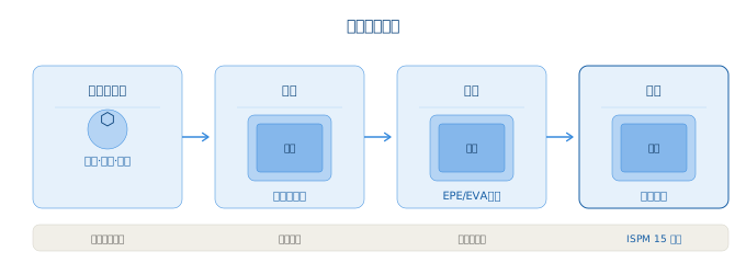
Packaging
| Layer | Material | Standard |
|---|---|---|
| Circuit prep | Drained + anti-rust treatment | All liquid ports capped |
| Inner | Moisture-proof sealed bag | Fully sealed |
| Middle | Custom foam buffer (EPE/EVA) | Molded to equipment shape |
| Outer | Fumigated wooden crate | ISPM 15 compliant |
Logistics
| Method | Transit time | Use case |
|---|---|---|
| Sea freight | 4–6 weeks to major European ports (Hamburg, Rotterdam, Antwerp) | Standard projects |
| Air freight | 5–7 days | Urgent projects, small quantities |
Documents dispatched with shipment: commercial invoice, packing list, certificate of origin, bill of lading.
Receiving Inspection
| Step | Check |
|---|---|
| 1. External packaging | Crate damage, water stains, tipping marks |
| 2. Unpack and verify | Model, quantity, accessories (cables, comms lines, mounting hardware, manuals) |
| 3. Visual inspection | Panel, ports, piping — any transit damage |
| 4. Piping | All liquid port caps secure and in place |
| 5. Electrical compartment | No loose wiring, no foreign objects |
| 6. Power-on (optional) | Power up without load, confirm control system boots |
Any anomalies: photograph and contact the supplier immediately. Transit damage claims must be filed within 48 hours of delivery.
Installation and Commissioning
Duration: 2–3 working days.
| Step | Activity |
|---|---|
| Positioning | Mechanical fixing, confirm cabinet level |
| Piping | Liquid cooling line connection, seal check |
| Electrical | Power, communication, grounding |
| Fill and bleed | Inject coolant, bleed air from lines |
| Power-up init | Control system startup, parameter verification |
| Trial run | Low load to full load, step-by-step validation |
Installation can be done by the customer's team (with installation manual and remote video support) or with a supplier engineer on site.
Training included
Half-day hands-on: startup, shutdown, parameter setting, emergency procedures. English manuals provided.
Remote support
Video-assisted commissioning available for teams doing self-installation.
4. Testing and Maintenance
Test Scenarios
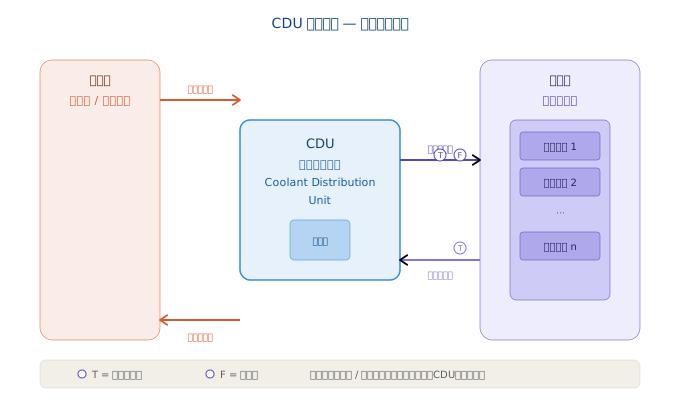
Scenario 1: CDU Performance Validation
Connect the load bank to the CDU secondary loop. Step-load as follows:
| Step | Duration | Recorded parameters |
|---|---|---|
| 25% | 30–60 min | Primary supply/return temperatures, secondary supply/return temperatures |
| 50% | 30–60 min | Primary/secondary flow rates |
| 75% | 30–60 min | CDU actual vs. design heat exchange capacity |
| 100% | 30–60 min | Full parameter set |
Pass criterion: secondary supply temperature within design range (typically ±1 °C) at all load steps. Heat exchange efficiency ≥ 95% of design value.
Scenario 2: Full-Load Simulation
When servers are not yet deployed or only partially installed, the load bank simulates the thermal load of a fully populated rack. A server power profile file can be imported to replicate real load patterns. Verification points:
- Temperature stability under full thermal load
- Coolant flow distribution uniformity across racks
- Temperature rise trend during extended full-load operation
Scenario 3: Generator + Liquid Cooling Integrated Test
Simulate a utility power failure and verify:
| Check | Focus |
|---|---|
| Generator start | Start time (typically 10–15 s) |
| Load recovery | Load bank restores pre-outage power setting |
| Full-load run | Frequency stability, voltage stability, fuel consumption rate |
| Cooling system recovery | CDU restart and temperature recovery time |
Post-Test Procedure (Important)
The load bank itself does not contain coolant — coolant comes from the site CDU or cooling loop. After every test:
| Step | Action | Purpose |
|---|---|---|
| 1. Drain | Open drain valve, fully empty internal cooling circuit | Prevent stagnant liquid from causing corrosion or microbial growth |
| 2. Blow out | Use clean, oil-free, dry compressed air from inlet side until no droplets at outlet | Clear residual liquid from dead legs |
| 3. Cap ports | Install caps on all liquid interfaces | Prevent dust and debris ingress |
| 4. Visual check | Confirm exterior is dry, no liquid stains | Quick status confirmation before next use |
For long-term storage, apply anti-rust treatment to internal piping after draining and blow-out.
Routine Maintenance
| Item | Interval | Action |
|---|---|---|
| Pipe connections | Monthly | Visual inspection of all fittings, flanges, valves for leakage traces |
| Electrical terminals | Quarterly | Power off, check for loose connections. Replace discolored or oxidized terminals. |
| Ground check | Quarterly | Measure ground resistance, confirm no corrosion or breakage |
| Safety protection function | Every 6 months | Trigger over-temp, leak, and flow protections one by one, verify correct response |
| Heat exchanger inspection | As needed | If temperature uniformity test shows abnormal ΔT, check flow channels for scaling or blockage |
| HMI / host software | As needed | Check software version, confirm data logging and export functions |
This article reflects our experience delivering rack-mounted liquid-cooled load banks. Specifications may vary by project. For a specific quotation or technical discussion, please contact us.